ModelEditor
Features
- Create UML-alike models
- Store models and diagrams in a single xml file
- Create structured diagrams with packages, classes, components, use-cases
- Edit element properties including multi-selection (e.g. change color of many elements at once)
- Design your diagrams with only a few clicks thanks to automatic coloring, easy alignment and automatic layout of labeling
- Add C++ classes and components by simply dragging files from project explorer on diagrams
- Navigate from class on diagram to source code
- Configure your own model elements with custom icons
Screenshots
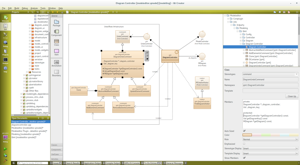
Several features help designing beautiful diagrams easily:
- Create a "Boundary" box with a dotted border and a title. Everything within that box will move as a group if you drag the box.
- Use Shift-Click on a relation to create a new sampling point. Use Ctrl-Click on a sampling point to remove it again.
- If possible the connection between an end-point of a relation and its neighbored sampling point is automatically drawn vertically or horizontally by moving the end-point.
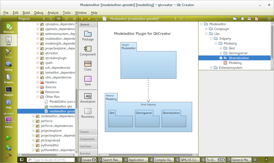
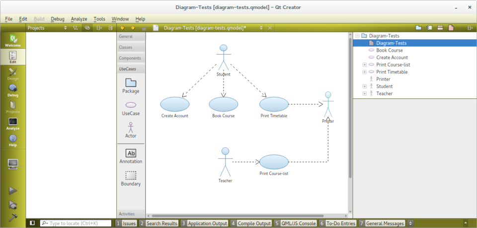
The elements for use-case diagrams (and activity diagrams) are configured with icon and color using a simple def-file format.
Example:
Icon UseCase
    Title: "Use-Case"
    Elements: item
    Stereotype: 'usecase'
    Display: icon
    Width: 40
    Height: 20
    BaseColor: #5fb4f0
Begin
    Ellipse 20, 10, 20, 10
End
With that def-file one can introduce new icons for stereotypes (e.g. the Entity, Boundary and Control icons for classes), new elements (e.g. the Use Case, Actor) or tool-bars.
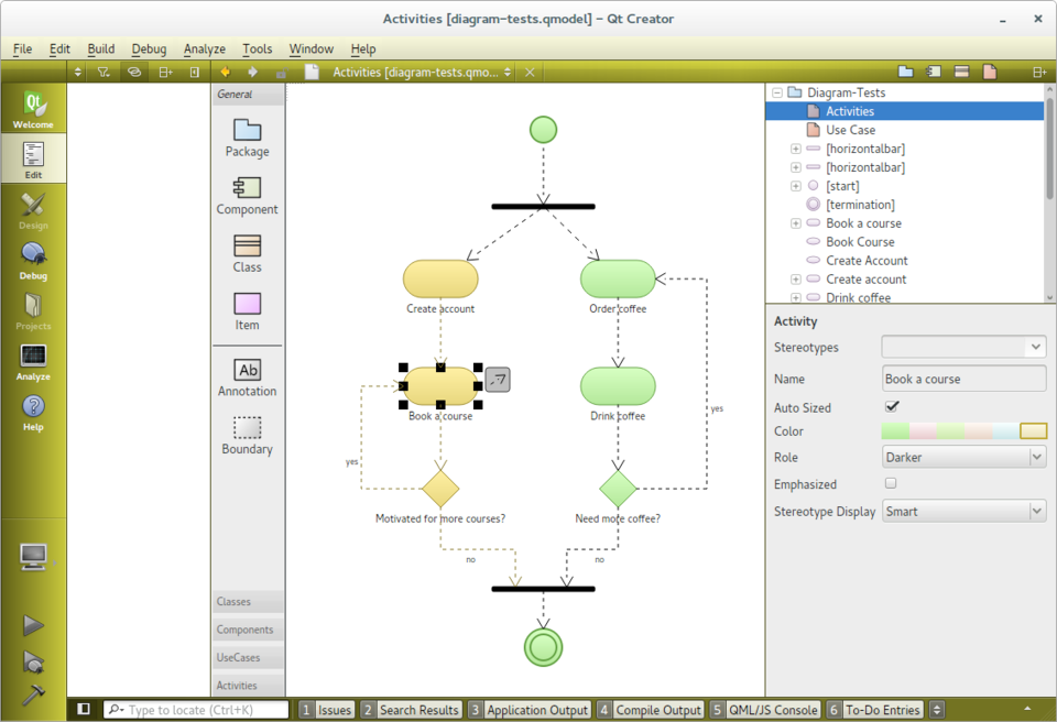
- Use multi-selection to align elements easily.
- Change color or stereotype of all selected elements simultaneously.
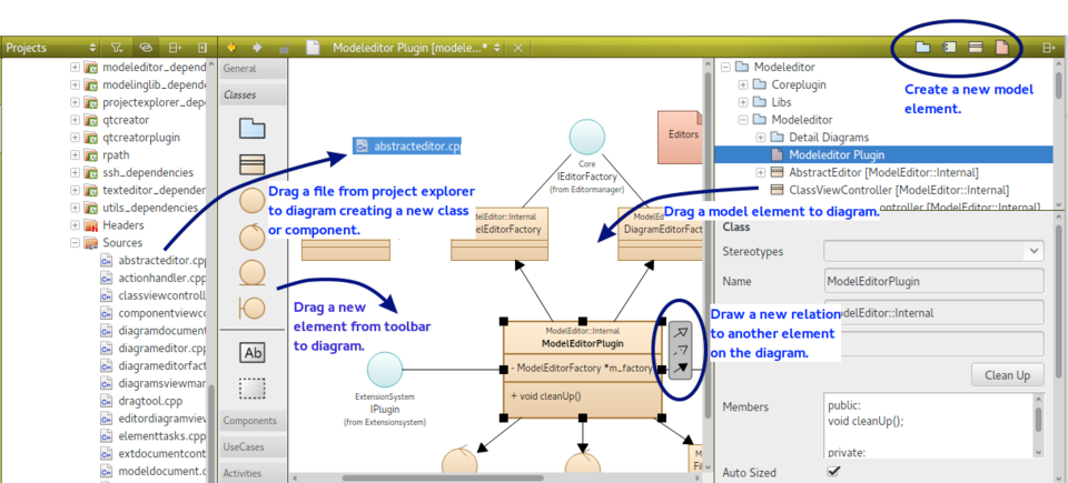
- Press one of the small buttons in the upper right toolbar to add a new element to the model
- Drag an icon from the toolbar to a diagram to create a new element
- Drag a model element from the model tree to a diagram to add the element and all its relations to the diagram.
- Drag a C++ source code from the project explorer to a diagram to add the file as a component or any of its declared classes.
- Drag one of the arrows right to a selected element to another element on the diagram to create a new relation
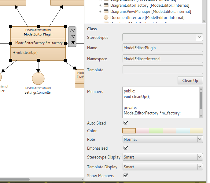
- This is not standard UML: A namespace property
- The attributes and methods are written as C++ declarations.
- Only a few properties define the look of the elements: a color, a role and an extra enhancement flag.